|
By Eric Lawrey, Copyright 1997-2001
The telecommunications industry faces the
problem of providing telephone services to rural areas, where the customer
base is small, but the cost of installing a wired phone network is very
high. One method of reducing the high infrastructure cost of a wired system
is to use a fixed wireless radio network. The problem with this is that
for rural and urban areas, large cell sizes are required to obtain sufficient
coverage. This results in problems cased by large signal path loss and
long delay times in multipath signal propagation.
Currently Global System for Mobile telecommunications
(GSM) technology is being applied to fixed wireless phone systems in rural
areas or Australia. However, GSM uses Time Division Multiple Access (TDMA),
which has a high symbol rate leading to problems with multipath causing
inter-symbol interference.
Several techniques are under consideration
for the next generation of digital phone systems, with the aim of improving
cell capacity, multipath immunity, and flexibility. These include Code
Division Multiple Access (CDMA) and Coded Orthogonal Frequency Division
Multiplexing (COFDM). Both these techniques could be applied to providing
a fixed wireless system for rural areas. However, each technique has different
properties, making it more suited for specific applications.
COFDM is currently being used in several
new radio broadcast systems including the proposal for high definition
digital television, Digital Video Broadcasting (DVB) and Digital Audio
Broadcasting (DAB). However, little research has been done into the use
of COFDM as a transmission method for mobile telecommunications systems.
With CDMA systems, all users transmit in
the same frequency band using specialized codes as a basis of channelization.
The transmitted information is spread in bandwidth by multiplying it by
a wide bandwidth pseudo random sequence. Both the base station and the
mobile station know these random codes that are used to modulate the data
sent, allowing it to de-scramble the received signal.
OFDM/COFDM allows many users to transmit
in an allocated band, by subdividing the available bandwidth into many
narrow bandwidth carriers. Each user is allocated several carriers in which
to transmit their data. The transmission is generated in such a way that
the carriers used are orthogonal to one another, thus allowing them to
be packed together much closer than standard frequency division multiplexing
(FDM). This leads to OFDM/COFDM providing a high spectral efficiency.
1.1 Third Generation Wireless Networks
The expansion of the use of digital networks
has led to the need for the design of new higher capacity communications
networks. The demand for cellular-type systems in Europe is predicted to
be between 15 and 20 million users by the year 2000 [1], and is already
over 30 million (1995) in the U.S. [2]. Wireless services have been growing
at a rate greater than 50% per year [2], with the current second-generation
European digital systems (GSM) being expected to be filled to capacity
by the early 2000’s[3]. The telecommunications industry is also changing,
with a demand for a greater range of services such as video conferencing,
Internet services, and data networks, and multimedia. This demand for higher
capacity networks has led to the development of third generation telecommunications
systems.
One of the proposed third generation telecommunications
systems is the Universal Mobile Telecommunications System (UMTS), which
aims to provide a more flexible data rate, a higher capacity, and a more
tightly integrated service, than current second generation mobile systems.
This section focuses on the services and aims of the UMTS. Other systems
around the world are being developed, however many of these technologies
are expected to be eventually combined into the UMTS.
The World Wide Web (WWW) has become an
important communications media, as its use has increased dramatically over
the last few years. This has resulted in an increased demand for computer
networking services. In order to satisfy this, telecommunications systems
are now being used for computer networking, Internet access and voice communications.
A WWW survey revealed that more then 60% of users access the Internet from
residential locations [10], where the bandwidth is often limited to 28.8kbps
[8]. This restricts the use of the Internet, preventing the use of real
time audio and video capabilities. Higher speed services are available,
such as integrated-services digital network (ISDN). These provide data
rates up to five times as fast, but at a much-increased access cost. This
has led to the demand of a more integrated service, providing faster data
rates, and a more universal interface for a variety of services. The emphasis
has shifted away from providing a fixed voice service to providing a general
data connection that allows for a wide variety of applications, such as
voice, Internet access, computer networking, etc.
The increased reliance on computer networking
and the Internet has resulted in demand for connectivity to be provided
“any where, any time”, leading to an increase in the demand for wireless
systems. This demand has driven the need to develop new higher capacity,
high reliability wireless telecommunications systems.
The development and deployment of third
generation telecommunication systems aim to overcome some of the downfalls
of current wireless systems by providing a high capacity, integrated wireless
network. There are currently several third generation wireless standards,
including UMTS, cdmaOne, IMT 2000, and IS-95 [10].
1.1.1 Evolution of Telecommunication Systems.
Many mobile radio standard have been developed
for wireless systems throughout the world, with more standards likely to
emerge.
Most first generations systems were introduced
in the mid 1980’s, and can be characterized by the use of analog transmission
techniques, and the use of simple multiple access techniques such as Frequency
Division Multiple Access (FDMA). First generation telecommunications systems
such as Advanced Mobile Phone Service (AMPS) [4] only provided voice communications.
They also suffered from a low user capacity, and security problems due
to the simple radio interface used.
Second generation systems were introduced
in the early 1990’s, and all use digital technology. This provided an increase
in the user capacity of around three times [6]. This was achieved by compressing
the voice waveforms before transmission [7].
Third generation systems are an extension
on the complexity of second-generation systems and will begin roll out
of services sometime after the year 2001. The capacity of third generation
systems is expected to be over ten times original first generation systems.
This is going to be achieved by using complex multiple access techniques
such as CDMA, or an extension of TDMA, and by improving flexibility of
services available.
Table 1 and Table 2 show some of the major
cellular mobile phone standards in North America and Europe.
| Cellular System |
Year of Introduction |
Transmission Type |
Multiple Access Technique |
Channel Bandwidth |
System Generation |
| Advanced Mobile Phone System (AMPS) |
1983 |
Analog |
FDMA |
30kHz |
First |
| Narrowband AMPS (NAMPS) |
1992 |
Analog |
FDMA |
10kHz |
First |
| U.S. Digital Cellular (USDC) |
1991 |
Digital |
TDMA |
30kHz |
Second |
| U.S Narrowband Spread Spectrum(IS-95) |
1993 |
Digital |
CDMA |
1.25MHz |
Second |
| Wideband cdmaOne |
2000 |
Digital |
CDMA |
- |
Third |
Table 1 Major Mobile Standards in North America[6]
| Cellular System |
Year of Introduction |
Transmission Type |
Multiple Access Technique |
Channel Bandwidth |
System Generation |
| E-TACS |
1985 |
Analog |
FDMA |
25kHz |
First |
| NMT-900 |
1986 |
Analog |
FDMA |
12.5kHz |
First |
| Global System for Mobile (GSM) |
1990 |
Digital |
TDMA |
200kHz |
Second |
| Universal Mobile Tele-communications System (UMTS) |
>2000 |
Digital |
CDMA/ TDMA |
- |
Third |
Table 2 Major Mobile Standards in Europe[6]
Figure 1 shows the evolution of current
services and networks to the aim of combining them into a unified third
generation network. Many currently separate systems and services such as
radio paging, cordless telephony, satellite phones, private radio systems
for companies etc, will be combined so that all these services will be
provided by third generation telecommunications systems.
Figure 1 Evolution of current networks
to the next generation of wirless networks (reproduced from [1])
1.1.2 Overall Aims of Universal Mobile Telecommunications System
The main aims of the Universal Mobile Telecommunications
System is to provide a more unified high capacity network, in wireless
and wired environments. UMTS will enable fixed and wireless services to
converge. There are to be three main channel capacity connections: a mobile
rate of 144kbps; a portable rate of 384kbps and an in-building rate of
2Mbps [10]. It will have the capacity to provide services and features
requiring less then 2Mbps that would otherwise have been provided with
a fixed network. UMTS must therefore provide on-demand, variable bandwidth
allocation. It will also combine a range of applications including cordless
phones, cellular phones, and mobile data networking for personal, business
and residential use.
1.1.3 Teleservices
Many services have been identified for
the UMTS, which can be categorized based on the data rate required, quality
of service (reliability and allowable bit error rate (BER)), real time
transfer rate. Each of the services has different characteristics in terms
of delay tolerance and allowable bit error rates. Table 3 shows characteristics
for some of the UMTS services.
| Applications or Services |
Data Rate Required |
Quality of service required |
Time critical data |
| Messaging (email, etc) |
Low (1-10kbps) |
High |
No |
| Voice |
Low (4-20kpbs) |
Low (BER < 1e-3) |
Yes |
| Web browsing |
As high as possible (>10kbps-100kbps) |
High (BER < 1e-9) |
Depends on material. Generally not time critical. |
| Videoconferencing |
High (100kbps-1Mbps) |
Medium |
Yes |
| Video Surveillance |
Medium (50-300kbps) |
Medium |
No |
| High Quality Audio |
High (100-300kbps) |
Medium |
Yes |
| Database access |
High (>30kbps) |
Very High |
No |
Table 3 UMTS Services, showing the data characteristics of each service
The data characteristics will determine
the most suitable transmission methods. The type of data associated with
each service determines the type of environment in which the service can
be supported.
1.1.4 UMTS Environments
The aim of the UMTS systems is to provide
an “any where, any time” service, thus the operating environment will vary
depending on the user location. The environment in which the wireless system
must operate affects the system capacity and type of services that can
be provided. Table 4 lists some of the environments in which UMTS will
be required to provide coverage.
| Environment |
Maximum supported Data Rate |
| Business (indoor) |
384kbps |
| Suburban (indoor/outdoor) |
144kbps |
| Urban vehicular (outdoor) |
144kbps |
| Urban pedestrian (outdoor) |
144kbps |
| Fixed (Outdoor) |
144kbps / 384kbps |
| Local high bit rate (Indoor) |
2Mbps |
Table 4 Maximum supported data rates for UMTS, for various environments.
The maximum supported data rate for each
environment is related to the cell size required to provide adequate coverage
for the environment.
1.1.5 Cell types
A cellular network is required to ensure
the UMTS can provide a high capacity network. As with any cellular system,
the total capacity of the network is dependent on the size of the cells
used. The smaller the cells are made, the larger the total capacity. However,
the cell size is limited by the amount of infrastructure. The cell size
also determines the maximum channel capacity for each cell, as propagation
effects, such as multipath delay spread and high path loss, force large
cells to have a lower data rate. Large cells also have to service a large
number of users, and since the cell capacity is approximately fixed, each
user can only have a reduced data rate, with respect to a smaller cell.
In order to optimise the cellular network three cell types are used. These
are the pico-cell, micro cell, and macro-cell. The three different cell
types trade off cell size will total capacity and services. Table 5 shows
the three cell types used in the UMTS system and some of the cell characteristics.
| |
Pico-cell |
Micro-cell |
Macro-cell |
| Cell radius |
<100m |
<1000m |
<20km |
| Antenna |
Ceiling/wall mounted |
Below roof top height |
Roof top mounting |
| Max. multipath delay spread |
1 msec |
5 msec |
20 msec |
| Applications and environments |
Indoor/Outdoor
Within buildings
City centres
Local high bit rate |
High density outdoor
Business (indoor)
Fixed (Outdoor)
Inner city areas |
Low density areas
Suburban areas
Urban areas
Fixed (outdoor) |
| Services and data rate supported |
All services (up to 2Mbps) |
Up to 384kbps |
Limited sub-set
(up to 144kpbs) |
Table 5 Cell Types used in UTMS
The size and type of coverage of each cell
type effects the radio propagation problems that will be encountered. This
will determine the most suitable radio transmission technique to use.
1.1.6 Radio Interface
One of the aims identified for UMTS is
to provide a wireless interface comparable to wired connections. The requirement
to provide wide band services up to 2Mb/s, with flexible, on demand allocation
of transmission capacity in a large range of radio environments, will call
for a revolution in the radio access techniques used.
The radio interface is currently undergoing
substantial research, with the relative performance of CDMA and TDMA being
investigated [9]. Currently CDMA appears to be the most likely candidate
for supporting the high data rate required. However, other techniques such
as COFDM and hybrid solutions may also be appropriate for UMTS.
1.1.7 Satellite Networking
One of the aims of the UMTS is to provide
access “any where, any time”. However, cellular networks can only cover
a limited area due to the high infrastructure costs. For this reason, satellite
systems will form an integral part of the UMTS network. Satellites will
be able to provide an extended wireless coverage to remote areas and to
aeronautical and maritime mobiles. The level of integration of the satellite
systems with the terrestrial cellular networks is under investigation.
A fully integrated solution will require mobiles to be dual mode terminals
that would allow communications with orbiting satellites and terrestrial
cellular networks. Low Earth Orbit (LEO) satellites are the most likely
candidates for providing worldwide coverage.
Currently several low earth orbit satellite
systems are being deployed for providing global telecommunications. These
include the Teledesic System, which is scheduled to begin operation by
the end of 2002 with 288 satellites [10], to provide high bandwidth two-way
communications to virtually anywhere in the world. However, the Teledesic
System will not be able to meet even 20% of the demand [10], thus the need
for broadband wireless networks.
(Addendum,
10/2001: Current estimates put the release date of the Teledesic System
sometime in 2005, see www.teledesic.com).
1.1.8 Timetable for System Implementation
Across the globe, each region is moving
to make third generation systems happen. Japan is looking at having a system
up and running by year 2001. This is driven by the very high demand for
mobile communications, which has been so great that their second-generation
cellular networks are starting to run out of capacity [10]. It is expected
that Europe will have a wide band CDMA system by the year 2005 [10]. The
U.S. is expected to implement a third generation system somewhere from
2000 to 2010 [10].
Manufacturers are creating several standards
to meet requirements in each sector of the world. To date, the majority
of systems are based on CDMA standards. Before infrastructure rolls out,
third generations will be developed on a regional basis.
This process is being guided by the International
Telecommunications Union’s (ITU) effort to create the IMT 2000 standard.
ITU will produce the IMT 2000 standard by the year 2000, with the aim of
combining the regional systems into a unified standard [10].
1.1.9 Conclusion
Future communications will be driven by
the need to provide a more integrated high capacity, wide coverage service.
For the 21st century user there should ideally be no distinction
in service capability between mobile or fixed network access. This will
be achieved using a variety of technologies including satellite communications,
advanced radio networking techniques, and high speed fixed networks.
1.2 Propagation Characteristics of mobile radio channels
In an ideal radio channel, the received
signal would consist of only a single direct path signal, which would be
a perfect reconstruction of the transmitted signal. However in a real channel,
the signal is modified during transmission in the channel. The received
signal consists of a combination of attenuated, reflected, refracted, and
diffracted replicas of the transmitted signal. On top of all this, the
channel adds noise to the signal and can cause a shift in the carrier frequency
if the transmitter, or receiver is moving (Doppler effect). Understanding
of these effects on the signal is important because the performance of
a radio system is dependent on the radio channel characteristics.
1.2.1 Attenuation
Attenuation is the drop in the signal power
when transmitting from one point to another. It can be caused by the transmission
path length, obstructions in the signal path, and multipath effects. Figure
2 shows some of the radio propagation effects that cause attenuation. Any
objects that obstruct the line of sight signal from the transmitter to
the receiver can cause attenuation.
Figure 2 Radio Propagation Effects
Shadowing of the signal can occur whenever
there is an obstruction between the transmitter and receiver. It is generally
caused by buildings and hills, and is the most important environmental
attenuation factor.
Shadowing is most severe in heavily built
up areas, due to the shadowing from buildings. However, hills can cause
a large problem due to the large shadow they produce. Radio signals diffract
off the boundaries of obstructions, thus preventing total shadowing of
the signals behind hills and buildings. However, the amount of diffraction
is dependent on the radio frequency used, with low frequencies diffracting
more then high frequency signals. Thus high frequency signals, especially,
Ultra High Frequencies (UHF), and microwave signals require line of sight
for adequate signal strength. To over come the problem of shadowing, transmitters
are usually elevated as high as possible to minimise the number of obstructions.
Typical amounts of variation in attenuation due to shadowing are shown
in Table 6.
| Description |
Typical Attenuation due to Shadowing |
| Heavily built-up urban centre |
20dB variation from street to street |
| Sub-urban area (fewer large buildings) |
10dB greater signal power then built-up urban center |
| Open rural area |
20dB greater signal power then sub-urban areas |
| Terrain irregularities and tree foliage |
3-12dB signal power variation |
Table 6 Typical shadowing in a radio channel (Values from [11])
Shadowed areas tend to be large, resulting
in the rate of change of the signal power being slow. For this reason,
it is termed slow-fading, or log-normal shadowing.
1.2.2 Multipath Effects
1.2.2.1 Rayleigh fading
In a radio link, the RF signal from the
transmitter may be reflected from objects such as hills, buildings, or
vehicles. This gives rise to multiple transmission paths at the receiver.
Figure 3 show some of the possible ways in which multipath signals can
occur.
Figure 3 Multipath Signals
The relative phase of multiple reflected
signals can cause constructive or destructive interference at the receiver.
This is experienced over very short distances (typically at half wavelength
distances), thus is given the term fast fading. These variations can vary
from 10-30dB over a short distance. Figure 4 shows the level of attenuation
that can occur due to the fading.
Figure 4 Typical Rayleigh fading while the Mobile Unit is moving (for at 900 MHz)[15]
The Rayleigh distribution is commonly used
to describe the statistical time varying nature of the received signal
power. It describes the probability of the signal level being received
due to fading. Table 7 shows the probability of the signal level for the
Rayleigh distribution.
| Signal Level (dB about median) |
% Probability of Signal Level being less then the value given |
| 10 |
99 |
| 0 |
50 |
| -10 |
5 |
| -20 |
0.5 |
| -30 |
0.05 |
Table 7 Cummulative distribution for Rayleigh distribution (Value from [15])
1.2.2.2 Frequency Selective Fading
In any radio transmission, the channel
spectral response is not flat. It has dips or fades in the response due
to reflections causing cancellation of certain frequencies at the receiver.
Reflections off near-by objects (e.g. ground, buildings, trees, etc) can
lead to multipath signals of similar signal power as the direct signal.
This can result in deep nulls in the received signal power due to destructive
interference.
For narrow bandwidth transmissions if the
null in the frequency response occurs at the transmission frequency then
the entire signal can be lost. This can be partly overcome in two ways.
By transmitting a wide bandwidth signal
or spread spectrum as CDMA, any dips in the spectrum only result in a small
loss of signal power, rather than a complete loss. Another method is to
split the transmission up into many small bandwidth carriers, as is done
in a COFDM/OFDM transmission. The original signal is spread over a wide
bandwidth and so nulls in the spectrum are likely to only affect a small
number of carriers rather than the entire signal. The information in the
lost carriers can be recovered by using forward error correction techniques.
1.2.2.3 Delay Spread
The received radio signal from a transmitter
consists of typically a direct signal, plus reflections off objects such
as buildings, mountings, and other structures. The reflected signals arrive
at a later time then the direct signal because of the extra path length,
giving rise to a slightly different arrival times, spreading the received
energy in time. Delay spread is the time spread between the arrival of
the first and last significant multipath signal seen by the receiver.
In a digital system, the delay spread can
lead to inter-symbol interference. This is due to the delayed multipath
signal overlapping with the following symbols. This can cause significant
errors in high bit rate systems, especially when using time division multiplexing
(TDMA). Figure 5 shows the effect of inter-symbol interference due to delay
spread on the received signal. As the transmitted bit rate is increased
the amount of inter-symbol interference also increases. The effect starts
to become very significant when the delay spread is greater then ~50% of
the bit time.
Figure 5 Multipath Delay Spread
Table 8 shows the typical delay spread
for various environments. The maximum delay spread in an outdoor environment
is approximately 20 us, thus significant inter-symbol interference can
occur at bit rates as low as 25 kbps.
| Environment or cause |
Delay Spread |
Maximum Path Length Difference |
| Indoor (room) |
40 nsec - 200 nsec |
12 m - 60 m |
| Outdoor |
1 m sec - 20 m sec |
300 m - 6 km |
Table 8 Typical Delay Spread
Inter-symbol interference can be minimized
in several ways. One method is to reduce the symbol rate by reducing the
data rate for each channel (i.e. split the bandwidth into more channels
using frequency division multiplexing, or OFDM). Another is to use a coding
scheme that is tolerant to inter-symbol interference such as CDMA.
1.2.3 Doppler Shift
When a wave source and a receiver are moving
relative to one another the frequency of the received signal will not be
the same as the source. When they are moving toward each other the frequency
of the received signal is higher then the source, and when they are approaching
each other the frequency decreases. This is called the Doppler effect.
An example of this is the change of pitch in a car’s horn as it approaches
then passes by. This effect becomes important when developing mobile radio
systems.
The amount the frequency changes due to
the Doppler effect depends on the relative motion between the source and
receiver and on the speed of propagation of the wave. The Doppler shift
in frequency can be written:

(from [12])
Where Df
is the change in frequency of the source seen at the receiver , fo
is the frequency of the source, v is the speed difference between the source
and transmitter, and c is the speed of light.
For example: Let fo=
1GHz, and v = 60km/hr (16.7m/s) then the Doppler shift will be:
This shift of 55Hz in the carrier will
generally not effect the transmission. However, Doppler shift can cause
significant problems if the transmission technique is sensitive to carrier
frequency offsets (for example OFDM) or the relative speed is higher (for
example in low earth orbiting satellites).
1.3Multiple Access Techniques
Multiple access schemes are used to allow
many simultaneous users to use the same fixed bandwidth radio spectrum.
In any radio system, the bandwidth that is allocated to it is always limited.
For mobile phone systems the total bandwidth is typically 50 MHz, which
is split in half to provide the forward and reverse links of the system.
Sharing of the spectrum is required in order increase the user capacity
of any wireless network. FDMA, TDMA and CDMA are the three major methods
of sharing the available bandwidth to multiple users in wireless system.
There are many extensions, and hybrid techniques for these methods, such
as OFDM, and hybrid TDMA and FDMA systems. However, an understanding of
the three major methods is required for understanding of any extensions
to these methods.
1.3.1 Frequency Division Multiple Access
For systems using Frequency Division Multiple
Access (FDMA), the available bandwidth is subdivided into a number of narrower
band channels. Each user is allocated a unique frequency band in which
to transmit and receive on. During a call, no other user can use the same
frequency band. Each user is allocated a forward link channel (from the
base station to the mobile phone) and a reverse channel (back to the base
station), each being a single way link. The transmitted signal on each
of the channels is continuous allowing analog transmissions. The channel
bandwidth used in most FDMA systems is typically low (30kHz) as each channel
only needs to support a single user. FDMA is used as the primary subdivision
of large allocated frequency bands and is used as part of most multi-channel
systems.
Figure 6 and Figure 7 shows the allocation
of the available bandwidth into several channels.
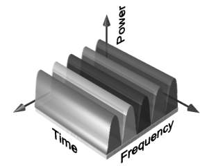
Figure 6 FDMA showing that the each narrow band channel is allocated to a single
user
Figure 7 FDMA spectrum, where the available bandwidth is subdivided into narrower
band channels
1.3.2 Time Division Multiple Access
Time Division Multiple Access (TDMA) divides
the available spectrum into multiple time slots, by giving each user a
time slot in which they can transmit or receive. Figure 8 shows how the
time slots are provided to users in a round robin fashion, with each user
being allotted one time slot per frame.
Figure 8 TDMA scheme where each user is allocated a small time slot
TDMA systems transmit data in a buffer
and burst method, thus the transmission of each channel is non-continuous.
The input data to be transmitted is buffered over the previous frame and
burst transmitted at a higher rate during the time slot for the channel.
TDMA can not send analog signals directly due to the buffering required,
thus is only used for transmitting digital data. TDMA can suffer from multipath
effects as the transmission rate is generally very high, resulting in significant
inter-symbol interference.
TDMA is normally used in conjunction with
FDMA to subdivide the total available bandwidth into several channels.
This is done to reduce the number of users per channel allowing a lower
data rate to be used. This helps reduce the effect of delay spread on the
transmission. Figure 9 shows the use of TDMA with FDMA. Each channel based
on FDMA, is further subdivided using TDMA, so that several users can transmit
of the one channel. This type of transmission technique is used by most
digital second generation mobile phone systems. For GSM, the total allocated
bandwidth of 25MHz is divided into 125, 200kHz channels using FDMA. These
channels are then subdivided further by using TDMA so that each 200kHz
channel allows 8-16 users [13].
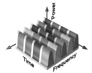
Figure 9 TDMA / FDMA hybrid, showing that the bandwidth is split into frequency
channels and time slots
1.3.3 Code Division Multiple Access
Code Division Multiple Access (CDMA) is
a spread spectrum technique that uses neither frequency channels nor time
slots. With CDMA, the narrow band message (typically digitised voice data)
is multiplied by a large bandwidth signal that is a pseudo random noise
code (PN code). All users in a CDMA system use the same frequency band
and transmit simultaneously. The transmitted signal is recovered by correlating
the received signal with the PN code used by the transmitter. Figure 10
shows the general use of the spectrum using CDMA.
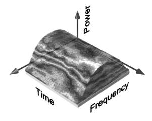
Figure 10 Code division multiple access (CDMA)
CDMA technology was originally developed
by the military during World War II [14]. Researchers were spurred into
looking at ways of communicating that would be secure and work in the presence
of jamming. Some of the properties that have made CDMA useful are:
-
· Signal hiding and non-interference
with existing systems.
-
· Anti-jam and interference rejection
-
· Information security
-
· Accurate Ranging
-
· Multiple User Access
-
· Multipath tolerance
For many years, spread spectrum technology
was considered solely for military applications. However, with rapid developments
in LSI and VLSI designs, commercial systems are starting to be used.
1.3.4 CDMA Process Gain
One of the most important concepts required
in order to understand spread spectrum techniques is the idea of process
gain. The process gain of a system indicates the gain or signal to noise
improvement exhibited by a spread spectrum system by the nature of the
spreading and despreading process. The process gain of a system is equal
to the ratio of the spread spectrum bandwidth used, to the original information
bandwidth. Thus, the process gain can be written as:

Where BWRF is the transmitted
bandwidth after the data is spread, and BWinfo is the bandwidth
of the information data being sent.
Figure 11 shows the process of a CDMA transmission.
The data to be transmitted (a) is spread before transmission by modulating
the data using a PN code. This broadens the spectrum as shown in (b). In
this example the process gain is 125 as the spread spectrum bandwidth is
125 times greater the data bandwidth. Part (c) shows the received signal.
This consists of the required signal, plus background noise, and any interference
from other CDMA users or radio sources. The received signal is recovered
by multiplying the signal by the original spreading code. This process
causes the wanted received signal to be despread back to the original transmitted
data. However, all other signals that are uncorrelated to the PN spreading
code become more spread. The wanted signal in (d) is then filtered removing
the wide spread interference and noise signals.
Figure 11 Basic CDMA transmission.
1.3.5 CDMA Generation
CDMA is achieved by modulating the data
signal by a pseudo random noise sequence (PN code), which has a chip rate
higher then the bit rate of the data. The PN code sequence is a sequence
of ones and zeros (called chips), which alternate in a random fashion.
Modulating the data with this PN sequence generates the CDMA signal. The
CDMA signal is generated by modulating the data by the PN sequence. The
modulation is performed by multiplying the data (XOR operator for binary
signals) with the PN sequence. Figure 12 shows a basic CDMA transmitter.
Figure 12 Simple direct sequence modulator
The PN code used to spread the data can
be of two main types. A short PN code (typically 10-128 chips in length)
can be used to modulate each data bit. The short PN code is then repeated
for every data bit allowing for quick and simple synchronization of the
receiver. Figure 13 shows the generation of a CDMA signal using a 10-chip
length short code. Alternatively a long PN code can be used. Long codes
are generally thousands to millions of chips in length, thus are only repeated
infrequently. Because of this they are useful for added security as they
are more difficult to decode.
Figure 13 Direct sequence signals
1.3.6 CDMA Forward Link Encoding
The forward link, from the base station
to the mobile, of a CDMA system can use special orthogonal PN codes, called
Walsh codes, for separating the multiple users on the same channel. These
are based on a Walsh matrix, which is a square matrix with binary elements
and dimensions that are a power of two. It is generated from the
basis that Walsh(1) = W1 = 0 and that:
Where Wn is the Walsh matrix
of dimension n. For example:

Walsh codes are orthogonal, which means
that the dot product of any two rows is zero. This is due to the fact that
for any two rows exactly half the number of bits match and half do not.
Each row of a Walsh matrix can be used
as the PN code of a user in a CDMA system. By doing this the signals from
each user is orthogonal to every other user, resulting in no interference
between the signals. However, in order for Walsh codes to work the transmitted
chips from all users must be synchronized. If the Walsh code used by one
user is shifted in time by more than about 1/10 of chip period, with respect
to all the other Walsh codes, it looses its orthogonal nature resulting
in inter-user interference. This is not a problem for the forward link
as signals for all the users originate from the base station, ensuring
that all the signal remain synchronized.
1.3.7 CDMA Reverse Link Encoding
The reverse link is different to the forward
link because the signals from each user do not originate from a same source
as in the forward link. The transmission from each user will arrive at
a different time, due to propagation delay, and synchronization errors.
Due to the unavoidable timing errors between the users, there is little
point in using Walsh codes as they will no longer be orthogonal. For this
reason, simple pseudo random sequences are typically used. These sequences
are chosen to have a low cross correlation to minimise interference between
users.
The capacity is different for the forward
and the reverse links because of the differences in modulation. The reverse
link is not orthogonal, resulting in significant inter-user interference.
For this reason the reverse channel sets the capacity of the system.
1.3.8 Orthogonal Frequency Division Multiplexing
Orthogonal Frequency Division Multiplexing
(OFDM) is a multicarrier transmission technique, which divides the available
spectrum into many carriers, each one being modulated by a low rate data
stream. OFDM is similar to FDMA in that the multiple user access is achieved
by subdividing the available bandwidth into multiple channels, which are
then allocated to users. However, OFDM uses the spectrum much more efficiently
by spacing the channels much closer together. This is achieved by making
all the carriers orthogonal to one another, preventing interference between
the closely spaced carriers.
Coded Orthogonal Frequency Division Multiplexing
(COFDM) is the same as OFDM except that forward error correction is applied
to the signal before transmission. This is to overcome errors in the transmission
due to lost carriers from frequency selective fading, channel noise and
other propagation effects. For this discussion the terms OFDM and COFDM
are used interchangeably, as the main focus of this thesis is on OFDM,
but it is assumed that any practical system will use forward error correction,
thus would be COFDM.
In FDMA each user is typically allocated
a single channel, which is used to transmit all the user information. The
bandwidth of each channel is typically 10 kHz-30 kHz for voice communications.
However, the minimum required bandwidth for speech is only 3 kHz. The allocated
bandwidth is made wider then the minimum amount required to prevent channels
from interfering with one another. This extra bandwidth is to allow for
signals from neighbouring channels to be filtered out, and to allow for
any drift in the centre frequency of the transmitter or receiver. In a
typical system up to 50% of the total spectrum is wasted due to the extra
spacing between channels. This problem becomes worse as the channel bandwidth
becomes narrower, and the frequency band increases.
Most digital phone systems use vocoders
to compress the digitised speech. This allows for an increased system capacity
due to a reduction in the bandwidth required for each user. Current vocoders
require a data rate somewhere between 4-13kbps [13], with depending on
the quality of the sound and the type used. Thus each user only requires
a minimum bandwidth of somewhere between 2-7 kHz, using QPSK modulation.
However, simple FDMA does not handle such narrow bandwidths very efficiently.
TDMA partly overcomes this problem by using
wider bandwidth channels, which are used by several users. Multiple users
access the same channel by transmitting in their data in time slots. Thus,
many low data rate users can be combined together to transmit in a single
channel that has a bandwidth sufficient so that the spectrum can be used
efficiently.
There are however, two main problems with
TDMA. There is an overhead associated with the change over between users
due to time slotting on the channel. A change over time must be allocated
to allow for any tolerance in the start time of each user, due to propagation
delay variations and synchronization errors. This limits the number of
users that can be sent efficiently in each channel. In addition, the symbol
rate of each channel is high (as the channel handles the information from
multiple users) resulting in problems with multipath delay spread.
OFDM overcomes most of the problems with
both FDMA and TDMA. OFDM splits the available bandwidth into many narrow
band channels (typically 100-8000). The carriers for each channel are made
orthogonal to one another, allowing them to be spaced very close together,
with no overhead as in the FDMA example. Because of this there is no great
need for users to be time multiplex as in TDMA, thus there is no overhead
associated with switching between users.
The orthogonality of the carriers means
that each carrier has an integer number of cycles over a symbol period.
Due to this, the spectrum of each carrier has a null at the centre frequency
of each of the other carriers in the system. This results in no interference
between the carriers, allowing then to be spaced as close as theoretically
possible. This overcomes the problem of overhead carrier spacing required
in FDMA.
Each carrier in an OFDM signal has a very
narrow bandwidth (i.e. 1 kHz), thus the resulting symbol rate is low. This
results in the signal having a high tolerance to multipath delay spread,
as the delay spread must be very long to cause significant inter-symbol
interference (e.g. > 100 msec).
1.3.9 OFDM generation
To generate OFDM successfully the relationship
between all the carriers must be carefully controlled to maintain the orthogonality
of the carriers. For this reason, OFDM is generated by firstly choosing
the spectrum required, based on the input data, and modulation scheme used.
Each carrier to be produced is assigned some data to transmit. The required
amplitude and phase of the carrier is then calculated based on the modulation
scheme (typically differential BPSK, QPSK, or QAM). The required spectrum
is then converted back to its time domain signal using an Inverse Fourier
Transform. In most applications, an Inverse Fast Fourier Transform (IFFT)
is used. The IFFT performs the transformation very efficiently, and provides
a simple way of ensuring the carrier signals produced are orthogonal.
The Fast Fourier Transform (FFT) transforms
a cyclic time domain signal into its equivalent frequency spectrum. This
is done by finding the equivalent waveform, generated by a sum of orthogonal
sinusoidal components. The amplitude and phase of the sinusoidal components
represent the frequency spectrum of the time domain signal. The IFFT performs
the reverse process, transforming a spectrum (amplitude and phase of each
component) into a time domain signal. An IFFT converts a number of complex
data points, of length that is a power of 2, into the time domain signal
of the same number of points. Each data point in frequency spectrum used
for an FFT or IFFT is called a bin.
The orthogonal carriers required for the
OFDM signal can be easily generated by setting the amplitude and phase
of each frequency bin, then performing the IFFT. Since each bin of an IFFT
corresponds to the amplitude and phase of a set of orthogonal sinusoids,
the reverse process guarantees that the carriers generated are orthogonal.
Figure 14 Basic FFT, OFDM transmitter and receiver
Figure 14 shows the configuration for a
basic OFDM transmitter and receiver. The signal generated is at base-band
and so to generate an RF signal the signal must be filtered and mixed to
the desired transmission frequency.
1.3.10 Adding a Guard Period to OFDM
One of the most important properties of
OFDM transmissions is its high level of robustness against multipath delay
spread. This is a result of the long symbol period used, which minimises
the inter-symbol interference. The level of multipath robustness can be
further increased by the addition of a guard period between transmitted
symbols. The guard period allows time for multipath signals from the pervious
symbol to die away before the information from the current symbol is gathered.
The most effective guard period to use is a cyclic extension of the symbol.
If a mirror in time, of the end of the symbol waveform is put at the start
of the symbol as the guard period, this effectively extends the length
of the symbol, while maintaining the orthogonality of the waveform. Using
this cyclic extended symbol the samples required for performing the FFT
(to decode the symbol), can be taken anywhere over the length of the symbol.
This provides multipath immunity as well as symbol time synchronization
tolerance.
As long as the multipath delay echoes stay
within the guard period duration, there is strictly no limitation regarding
the signal level of the echoes: they may even exceed the signal level of
the shorter path! The signal energy from all paths just add at the input
to the receiver, and since the FFT is energy conservative, the whole available
power feeds the decoder. If the delay spread is longer then the guard interval
then they begin to cause inter-symbol interference. However, provided the
echoes are sufficiently small they do not cause significant problems. This
is true most of the time as multipath echoes delayed longer than the guard
period will have been reflected of very distant objects.
Other variations of guard periods are possible.
One possible variation is to have half the guard period a cyclic extension
of the symbol, as above, an the other half a zero amplitude signal. This
will result in a signal as shown in Figure 15. Using this method the symbols
can be easily identified. This possibly allows for symbol timing to be
recovered from the signal, simply by applying envelop detection. The disadvantage
of using this guard period method is that the zero period does not give
any multipath tolerance, thus the effective active guard period is halved
in length. It is interesting to note that this guard period method has
not been mentioned in any of the research papers read, and it is still
not clear whether symbol timing needs to be recovered using this method.
Figure
15 Section of an OFDM signal showing 5 symbols, using a guard period which
is half a cyclic extension of the symbol, and half a zero amplitude signal.
(For a signal using a 2048 point FFT and 512 sample total guard period)
(Errata Note
10/2001: The best method for guard period implementation to use a cyclic
extension of the transmitted symbol over the entire guard period interval,
rather than only half of the guard period as described above).
Next Chapter 2
|